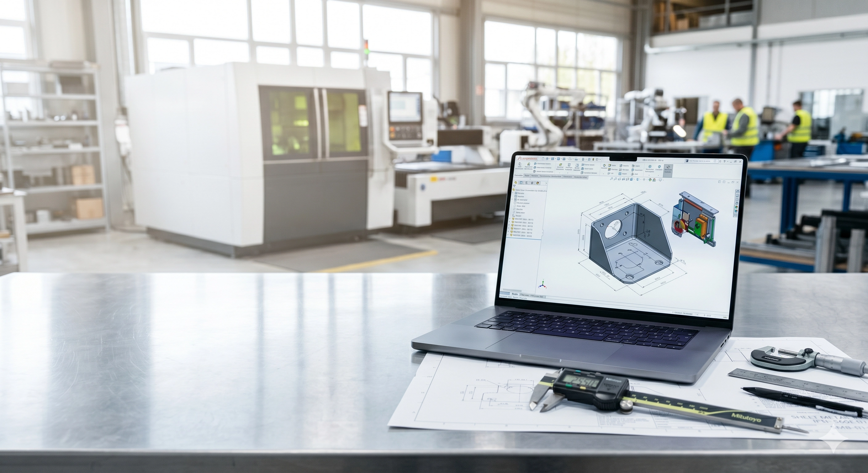
راهنمای فنی مهندسی برای ورقکاری صنعتی
تلرانسهای استاندارد مهندسی، محدودیتهای متریال و تنظیمات اولیه چیدمان. در گروه صنعتی اسپایک، ما معتقدیم که یک محصول بینقص با یک طراحی کاملاً استاندارد برای ساخت (DFM) آغاز میشود.
برای اطمینان از بهینهسازیِ طرحهای سفارشی شما جهت یک تولید یکپارچه و بدون خطا، اکیداً توصیه میکنیم استانداردهای مهندسی جامع ما را مطالعه فرمایید.
۱. یکپارچگی ضخامت دیواره
از آنجایی که قطعات ورقکاری از تا کردن و برش یک ورق تخت فلزی شکل میگیرند، مدل سهبعدی CAD شما باید در تمام مقاطع دارای ضخامت دیوارهی یکسانی باشد. این یک اصل حیاتی برای عملکرد صحیح ماشینآلات CNC و حفظ دقت ابعادی است.

۲. متریال قابل پردازش و محدودیتهای ابعاد ورق
تاسیسات ما برای پردازش طیف وسیعی از ورقهای خام درجهیک مجهز شده است، اما این پردازشها تابع محدودیتهای ابعادی مربوط به ضخامت فلز و دهانه دستگاه پرسبریک هستند.
| پارامترهای موجودی مواد | حداکثر آستانه تولید |
|---|---|
| حداکثر ابعاد چیدمان ورق تخت (Blank) | ۹۹۰ × ۱۱۹۳ میلیمتر (۳۹ × ۴۷ اینچ) |
| حداکثر طول خمکاری CNC پرسبریک | ۱۱۹۳ میلیمتر (۴۷ اینچ) |
| متریالهای استاندارد قابل پردازش | آلومینیوم، برنج، مس، استیل ضدزنگ، فولاد کربنی (سرد و گرم) |
۳. تلرانسهای استاندارد تولید
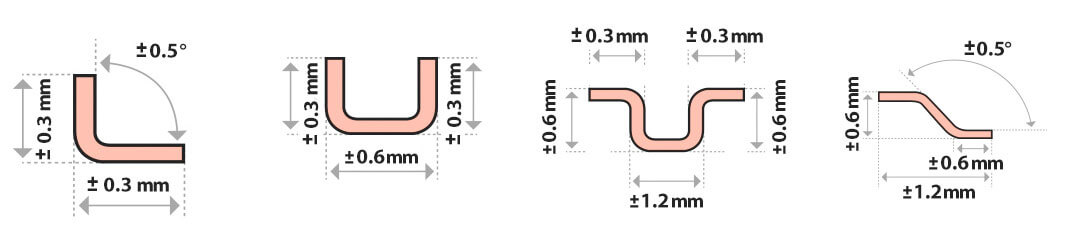
چنانچه مشتری نقشه مهندسی دقیق به همراه تلرانسگذاری (Print) ارائه ندهد، ما محصول را مستقیماً از روی فایل مدل سهبعدی و بر اساس تلرانسهای استاندارد زیر تولید خواهیم کرد:
| ویژگیهای تولید | محدوده تلرانس استاندارد (میلیمتر) |
|---|---|
| خمها (دقت زوایای فرمینگ) | ±۱° درجه |
| ابعاد خطی (به جز بخشهای خمدار) | ±۰.۱ میلیمتر |
| موقعیتها و فواصل خمکاری | ±۰.۴ الی ±۰.۵ میلیمتر |
| فاصله خم تا سوراخ یا ویژگیهای محلی | ±۰.۲ الی ±۰.۳۸ میلیمتر |
| قطر سوراخ و شیار / ابعاد لبهبهلبه | ±۰.۱۲۷ میلیمتر |
| قطر سوراخهای نیازمند اتصالات (مهره پرچی) | ±۰.۰۷۶ میلیمتر |
| ویژگیهایی که توسط ۲ خم یا بیشتر جدا شدهاند | ±۰.۷۶ میلیمتر |
| استاندارد زبری سطح | حداکثر ±۳.۲ میکرومتر |
۴. پارامترهای مهندسی خمکاری (K-Factor)
دینامیک خمکاری توسط محاسبات دقیق رفتار متریال تعیین میشود. در طول چرخه فرمینگ، "تار خنثی" (Neutral Axis) بدون تغییر باقی میماند و جابجایی نسبی آن مقدار K-Factor را برای محاسبه گسترده دقیق ورق در نرمافزارهای CAD مشخص میکند.
| روش خمکاری (محدوده شعاع: ۰ تا ۱×ضخامت) | مقدار مرجع K-Factor |
|---|---|
| خمکاری هوایی (Air Bending) - آلیاژهای نرم آلومینیوم | ۰.۳۳ |
| خمکاری هوایی - آلیاژهای سخت / استیل ضدزنگ | ۰.۴۰ |
| خمکاری هوایی - فولاد کربنی (نورد سرد و گرم) | ۰.۳۵ |
| خمکاری کفکوب (Bottom Bending) - آلومینیوم نرم | ۰.۴۲ |
| خمکاری کفکوب - استیل ضدزنگ | ۰.۴۶ |
۵. انتخاب شعاع خم داخلی (Inside Bend Radius)
ما تلرانس استاندارد صنعتی ±۱° را روی تمامی زوایای خم حفظ میکنیم. قالبهای استاندارد کارگاه ما از شعاعهای مقرونبهصرفهای که فوراً در دسترس اپراتور هستند پشتیبانی میکنند.
| شعاعهای استاندارد داخلی کارخانه | زمان راهاندازی ابزار (Lead Time) |
|---|---|
| ۰.۷۶ میلیمتر / ۱.۵۲ میلیمتر | موجودی استاندارد (فوری) |
| ۲.۲۸ میلیمتر / ۳.۰۴ میلیمتر | موجودی استاندارد (فوری) |
۶. حداقل طول فلنج و ارتفاع آفست (Z-Offset)
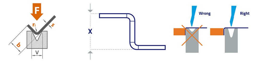
برای ایجاد یک فرم دقیق و پایدار، قطعه خام باید در سه نقطه با قالب (Die) تماس داشته باشد تا از سر خوردن ورق جلوگیری شده و زاویه دچار خطای اعوجاج نشود.
| ضخامت ورق (t) | حداقل طول فلنج (b) | حداقل ارتفاع آفست (X) |
|---|---|---|
| تا ۱.۰ میلیمتر | ۱۰.۰ میلیمتر | ۳۵.۰ میلیمتر |
| ۱.۲۵ میلیمتر | ۱۰.۵ میلیمتر | ۳۵.۰ میلیمتر |
| ۱.۵۰ میلیمتر | ۱۱.۰ میلیمتر | ۳۶.۰ میلیمتر |
| ۲.۰۰ میلیمتر | ۱۳.۵ میلیمتر | ۳۶.۵ میلیمتر |
| ۳.۰۰ میلیمتر | ۱۷.۰ میلیمتر | ۳۹.۵ میلیمتر |
۷. حداقل فاصله ویژگیها تا خط خم
فلز در مجاورت محور خم به طور طبیعی کشیده میشود. هرگونه بریدگی یا سوراخی که داخل این منطقه تغییر شکل (Deformation Zone) قرار گیرد، در معرض خطر جدیِ کشیدگی، تابخوردگی یا تغییر شکل قطرهاشکی قرار دارد.
| نوع هندسه برش | حداقل فاصله ایمن تا محور خم |
|---|---|
| فاصله لبه سوراخ گرد | ≥ ۵ × ضخامت ورق (t) + شعاع خم (r) |
| فاصله لبه شیار (Slot) | ≥ ۴ × ضخامت ورق (t) + شعاع خم (r) |

۸. استاندارد فواصل در نصب اتصالات پرچی و سختافزار
تعبیه رزوههای با مقاومت بالا از طریق مهرههای پرچی (PEM) یا جوش استاد (CD Studs), نیازمند رعایت فواصل دقیق از خطوط خم است تا مقاومت سازهای محلی حفظ شده و نشست موازی مهره تضمین گردد.
| پارامتر موقعیتدهی اتصالات | حداقل فاصله الزامی |
|---|---|
| فاصله لبه سوراخ پرچ تا مرز ورق | ≥ ۲ × ضخامت (t) [جلوگیری از بیرونزدگی ورق] |
| فاصله مرکز تا مرکز اتصالات مجاور | ≥ ۶ × ضخامت (t) [حفظ استحکام باربری] |
| مرکز پرچ تا خط مماس خم | ≥ ۵ × ضخامت (t) + شعاع خم + شعاع لبهبرگردان |
۹. طراحی لبهبرگردان (Hem) و ایمنی
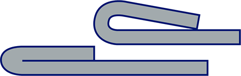
لبهبرگردانها (Hem) روشی عالی برای پنهان کردن پلیسههای خام، حذف لبههای تیز برای ایمنی دست اپراتور، و دو برابر کردن ضخامت موضعی در مناطقی هستند که به صلبیت ساختاری بالا نیاز دارند.
| پروفیل لبهبرگردان (Hem) | حداقل قطر داخلی | حداقل طول فلنج برگشتی |
|---|---|---|
| لبهبرگردان باز (Open Hem) | ≥ ۱.۰ × ضخامت متریال (t) | ≥ ۴ × ضخامت متریال (t) |
| لبهبرگردان بسته (Closed) | برابر با ضخامت متریال (t) | ≥ ۶ × ضخامت متریال (t) |
| پروفیل قطرهاشکی (Teardrop) | برابر با ضخامت متریال (t) | ≥ ۴ × ضخامت متریال (t) |
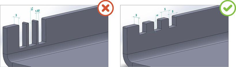
۱۰. قوانین ابعادی برای شاخکها و بریدگیها (Notches & Tabs)
بریدگیها (Notching) فلز را از لبههای بیرونی حذف میکنند تا امکان خمکاری بدون تداخل فراهم شود، در حالی که شاخکهای بیرونزده (Tabs) باعث سهولت همراستایی قطعات پیش از جوشکاری میشوند.
| نوع ویژگی | معیار حداقل عرض | حداکثر محدودیت عمق / طول |
|---|---|---|
| بریدگیهای فرمدهی (Notches) | ≥ ۱.۰ میلیمتر یا ۱.۰ × t (هر کدام بیشتر بود) | ≤ ۵ × عرض بریدگی [برای بریدگی V شکل: ≤ ۲ × عرض] |
| شاخکهای بیرونزده (Tabs) | ≥ ۲.۰ میلیمتر یا ۲.۰ × t (هر کدام بیشتر بود) | ≤ ۵ × عرض شاخک [برای جلوگیری از کمانش] |
۱۱. تلرانس و ابعاد خزینهکاری (Countersinks)
خزینهکاری به پیچهای سرتخت اجازه میدهد تا همسطح یا پایینتر از سطح ورق قرار گیرند. ما هم خزینهکاری ماشینکاری شده (با دریل) و هم خزینهکاری فرمدهی (با قالب پانچ) را ارائه میدهیم.
| فرآیند خزینهکاری | تلرانس کارخانه برای قطر بزرگ | قطر کوچک پیشنهادی |
|---|---|---|
| پردازش ماشینکاری (دریل) | ±۰.۲۵ میلیمتر [قطر بزرگ: ۲.۳ تا ۱۲.۷ میلیمتر] | ۲/۳ × ضخامت متریال (t) |
| پردازش فرمدهی (پرس پانچ) | ±۰.۳۸ میلیمتر [زوایای استاندارد: ۸۲°، ۹۰°، ۱۰۰°، ۱۲۰°] | ±۰.۳۸ میلیمتر (محدودیت قالب) |
۱۲. فرآیندهای پرداخت و پوشش سطح صنعتی
کارخانه ما مجموعه کاملی از گزینههای پوششدهی از جمله آنودایزینگ، آبکاری، پوشش PVD، سندبلاست، و رنگ پودری الکترواستاتیک پریمیوم را برای افزایش طول عمر و مقاومت در برابر خوردگی ارائه میدهد.
سوالات متداول
قیمتگذاری برش لیزر فایبر در گروه صنعتی اسپایک بر اساس فاکتورهای کلیدی نظیر نوع متریال (آهن، استیل، آلومینیوم)، ضخامت ورق، متر طول برش (یا تعداد سوراخها) و زمانسنجی ماشینآلات CNC انجام میشود. برای خدمات خمکاری پرسبریک نیز تعداد خطوط خم و پیچیدگی قطعه محاسبه میگردد.
برای قطعاتی که «فقط نیاز به برش لیزر» دارند، بهترین فرمتهای ارسالی DXF و DWG است. برای «قطعات خمدار»، فرمت STP مناسبترین انتخاب بوده و برای «مونتاژها و دستگاههای صنعتی»، ارائه فایل STP یا فایل اصلی سالیدورکز (SolidWorks) توصیه میشود. از نظر مهندسی، نرمافزار سالیدورکز بهترین و دقیقترین ابزار در حوزه طراحی ورقکاری است؛ همچنین برای طرحهای تزئینی و پروژههای گرافیکی، فرمت CorelDRAW (CDR) نیز در مجموعه ما قابل پردازش میباشد.
ضریب K-Factor و کسر خم به متغیرهایی همچون جنس ورق، ضخامت دقیق متریال، شعاع داخلی خم و دهانه قالب پرسبریک بستگی دارد. رعایت این پارامترها در طراحی فایل پیش از برش، از خطاهای ابعادی قطعه پس از خمکاری جلوگیری میکند.
به عنوان یک اصل استاندارد در طراحی برای ساخت (DFM)، قطر هیچکدام از سوراخها یا برشهای داخلی نباید کمتر از ضخامت خود ورق فلزی باشد (ترجیحاً معادل یا بیشتر از آن)، در غیر این صورت کیفیت لبهها افت کرده و پایداری قطعه به خطر میافتد.
بله، گروه صنعتی اسپایک به عنوان یک مرکز جامع خدمات ورقکاری، تمامی مراحل از برش لیزر فایبر، خمکاری CNC پرسبریک، جوشکاری تا رنگ پودری الکترواستاتیک کورهای را به صورت یکپارچه و با کنترل کیفیت دقیق انجام میدهد تا هزینهها و زمان تحویل به حداقل برسد.
بهینهسازی چیدمان قطعات (Nested)، استفاده از ضخامتهای تجاری موجود در بازار، کاهش تعداد قطعات مونتاژی با استفاده از طراحی خمهای بیشتر به جای جوشکاری، و رعایت اصول DFM از اصلیترین راههای کاهش هزینههای ساخت در اسپایک است.
برای داشتن فایل گسترده دقیق، طراحی باید در محیطهای تخصصی Sheet Metal (مانند سالیدورک) انجام شود و پارامترهای واقعی کارگاه شامل ضخامت دقیق ورق، شعاع داخلی ابزار پرسبرک و ضریب محاسبه خم (K-Factor یا Bend Deduction) بهطور دقیق در نرمافزار اعمال گردند تا پس از برش لیزر و خمکاری، ابعاد قطعه کاملاً اندازه و بدون تلرانس مونتاژی باشد.
ضریب K-Factor نسبت مکان خنثی (Neutral Axis) به ضخامت ورق است که رفتار فلز هنگام تغییر شکل را نشان میدهد. Bend Allowance (BA) طول قوس خم در ناحیه خنثی است، و Bend Deduction (BD) مقدار کسر از مجموع طول اضلاع بیرونی برای رسیدن به ابعاد تخت ورق است که طراحان برای محاسبه دقیق طول ابعاد اولیه (Blank) از آن استفاده میکنند.
در برش لیزر ورق آهن (کربن استیل)، استفاده از گاز اکسیژن باعث واکنش گرماده و افزایش سرعت برش میشود؛ در حالی که برای استنلس استیل و آلومینیوم از گاز نیتروژن با فشار بالا استفاده میشود تا لبههای کار کاملاً براق، بدون اکسیداسیون و آماده جوشکاری یا رنگآمیزی باقی بمانند.
این پدیده معمولاً زمانی رخ میدهد که شعاع خم داخلی کمتر از حد مجاز متریال باشد یا خط خم در راستای موازی با جهت نورد ورق (Fiber Direction) قرار گرفته باشد. راه حل آن افزایش شعاع خم داخلی متناسب با جدول DFM و عمود کردن خطوط خم نسبت به جهت نورد ورق است.
جوشکاری لیزری دارای سرعت بسیار بالا، تمرکز حرارتی بسیار موضعی (حداقل تغییر شکل حرارتی و تاببرداشتن ورق)، عمق نفوذ عالی و کیفیت ظاهر بسیار تمیز است که نیاز به عملیات تکمیلی، سنگزنی و پرداخت سطح را به حداقل میرساند.
اگر سوراخ یا برش لیزری بسیار به خط خم نزدیک باشد، در هنگام فرآیند پرسبریک دچار تغییر شکل (دفرمه شدن) میشود. به عنوان یک استاندارد مهندسی، فاصله لبه سوراخ تا خط خم باید حداقل برابر با ضخامت ورق به اضافه 1.5 برابر شعاع خم باشد.
مطالب مرتبط
آرشیو الگوهای برش لیزر · خدمات برش لیزر ورق فلزی · خمکاری CNC پرسبریک · هنر معماری فلزی