General
Tolerances
Uniform wall thickness
Internal radius
Min leg length
Min X-measurement for Z-bending
Min bend angle
Min distance from hole to bend-line
Notches and tabs
Collision with tools/machine
Box-shaped products
Min bend width
Min space between two settings
Hemming
sheet metal Design Guideline
To ensure your design would be accepted, we recommend you follow guidelines for working with sheet metal.


Engineers can prepare sheet-metal designs that are both highly functional and easy to make by the following Design for Manufacturing principles. Designers who adhere to the guidelines would finally achieve sheet-metal products with minimal waste and additional costs. The products are also less expensive and the possibilities of errors and rework are reduced. These guidelines are sets of recommendations towards good practice in sheet metal design. We are intended to give helpful advice to designers and developers.
General
■ The maximum sheet thickness for steel and aluminum is 10 mm.
■ The maximum sheet thickness for stainless steel is 8 mm.
■ The maximum length is 4000 mm.
■ These sizes are all compared to an angle of 90°. For a sharp bend, use wider dimensions for the groove.
Tolerances
Tolerances are always symmetrical relative to the nominal dimension.
■ Angle precision: ± 0.5˚ (± 30 minutes).
■ Leg length (per setting): ± 0.3 mm.
UNIFORM WALL THICkNESS
Because sheet metal parts are manufactured from a single sheet of metal the part must maintain a uniform wall thickness. We are capable of manufacturing sheet metal parts with a minimum of 0.5 mm. to 10 mm. in thickness.
Internal radius
The internal radius is determined by the tools in conjunction with the material properties.
Our preferred bend radius equals thickness plus 0.5mm (ri=th+0.5). The additional bend radius correction on your 3D model will be done by the specialized sheet metal software integrated with CNC press brake to reach the precise bending radius.
■ For reference, these internal radii can be used for an angle of 90 degrees.
Minimum leg length
This is the minimum overlay of the sheet on the mold that is necessary to perform the bending.
The required size of edge flanges is depended on bending tools size which is different in sheet thickness. See our preferred minimum size of edge flange per sheet thickness in the below table.
■ The minimum leg length (b) is determined by the sheet thickness.
Minimum X-measurement for Z-bending
An offset is used to create a “Z” shaped profile in a sheet metal part. The required offset height is depended on bending tools size which is different in sheet thickness.
In order to prevent collision with the tools during a “Z-bend”, it is necessary to take into account the minimum X-measurement shown in the table.
■ Please note: If the setting is sharper than 90 degrees, then the minimum leg length of a V-groove must be kept wider.
Minimum bend angle
Due to the rebound of the material, the sheet must always be bent a bit farther than the angle indicated. The tools have a minimum angle of 30˚, which allows for bends of up to 40˚ when you take the rebound into account.
Minimum distance from hole to bending line
Holes and slots should be a minimum of material thickness in diameter and away from sheet edge. The hole should be far enough away from the inner edge to avoid distortion. The minimum distance of Ymin can be determined by the formulas below.
Minimum distance for round holes
Ymin. = Rj + 2S
Minimum distance for rounded slots
L < 25: Ymin. = Rj + 3S
L ≥ 25: Ymin. = Rj + 4S
If the hole still has to be closer to the bend line, a cut can be made to the bend line.
Conditions for the cutting line:
■ Length = minimum length of hole (A)
■ Width = 0.8 x sheet thickness (B)
NOTCHES AND TABS
Notches must be at least the material’s thickness or 1mm., whichever is greater, and can be no longer than 5 times its width. Tabs must be at least 2 times the material’s thickness or 3mm., whichever is greater, and can be no longer than 5 times its width.
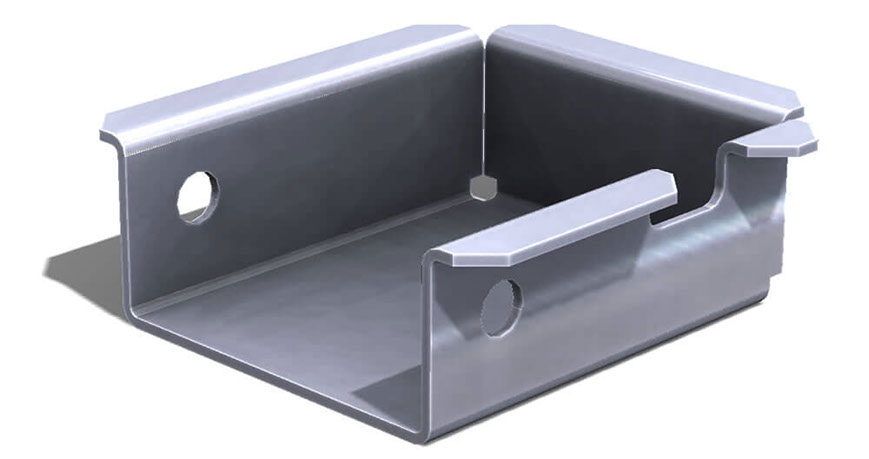
Collision with tools/machine
The ability to manipulate the material is largely dependent on the tools used. The Euro-10.047 tools are used to bend U-shapes. However, there is a limit to the feasible width/height ratio of the U shape. See the figures below to determine what the feasible width/height ratio is.
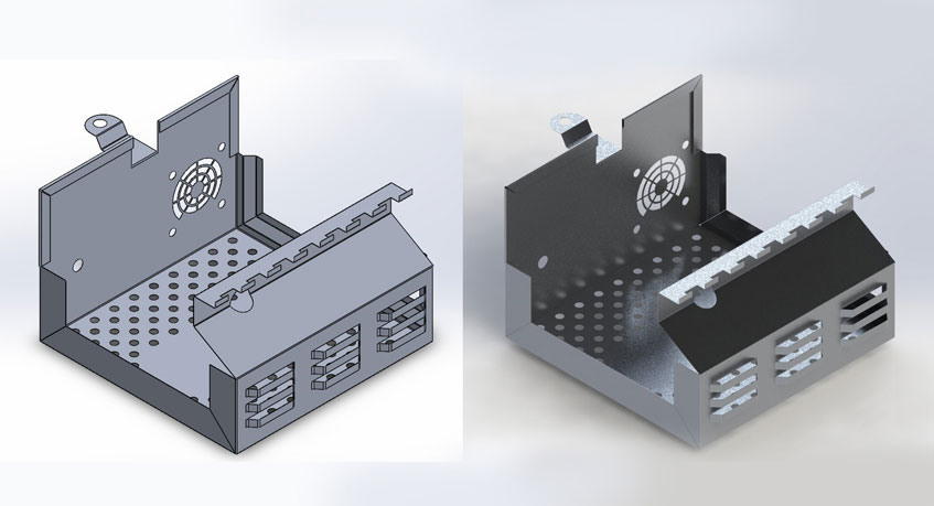
Box-shaped products
In order to prevent collision with the machine, the maximum height for box-shaped products is 120 mm.
Minimum bend width
Our narrowest tools are 20 mm. For bends such as those in the image below, this must be taken into account. This is why there must be enough room present for the mold in order to perform the bend.
In order to bend settings (into corners) such as those shown below, a cut must be made like the one displayed with the red lines.
This cut must be at least the same width as the side to be set.
Minimum space between two settings
The sides to be set (corners) cannot be drawn completely against each other due to our tolerances. In other words, the gap between the two sides should not be considered zero. We recommend leaving at least 0.5 mm of space between them.
Always take into account a minimum of 0.5 mm of space between the side to be set and the side that will remain flat.
Hemming
Hems are folds at the end of a part to create a rounded edge. We can form both open and closed hems as required. The tolerance of hem is dependent upon the hem’s radius, material thickness, and features near the hem. It is recommended the minimum inside diameter equals the material thickness and the hem return length is 4 times the thickness.
×
Our Capabilities
At Spike, we offer an end-to-end suite of sheet metal engineering and fabrication services. From design, 3D modeling, and fiber laser cutting to high-precision CNC bending, expert welding, powder coating, and final assembly. Whether you require a single functional prototype or high-volume industrial production, our engineering team ensures your drawings are executed with maximum precision, speed, and manufacturing flexibility.
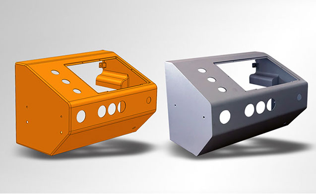
Gallery
Explore our gallery to see how Spike transforms technical drawings into high-quality metal components. Every project displayed here reflects our commitment to robust engineering, and flawless finishes—ranging from delicate industrial prototypes to large-scale architectural structures.
About Us
Spike is a premier provider of advanced sheet metal design and fabrication solutions. We simplify and accelerate your production cycle. Whether your project demands complex industrial enclosures or bespoke architectural metalwork, uncompromising precision is our signature standard.
Contact Us
EF
Address: No. 1, Block 24, Amirkabir Industrial Zone, Imam Khomeini Ave, Isfahan, Iran
Email: info@LaserSpike.com
Telegram: @SelSpike
Instagram: @LaserSpike
Central Hotline
+98 31 9100 4020
Sales & Engineering Support
+98 31 3131 5943 | +98 31 3131 5944
+98 31 9501 7300 | +98 31 9501 7500
RFQ & File Submission (Telegram / WhatsApp)
+98 905 752 0383
Management:+98 912 671 6499
+98 913 796 2046
+98 913 323 9059
How to Order
Easy online ordering from anywhere across the country. Simply send your technical drawings or CAD files via Telegram or Eitaa.
Contact: +98 905 752 0383
Sheet Metal Design Guide
Adhering to Design for Manufacturing (DFM) principles empowers engineers and designers to create highly functional, manufacturing-ready sheet metal parts. Following these technical guidelines minimizes unnecessary production costs and eliminates material waste.
To ensure your custom designs are fully optimized for seamless production, we highly recommend reviewing our comprehensive engineering standards.
Laser Cut Patterns
A comprehensive collection of custom graphic patterns optimized for decorative laser cutting is available in our exclusive archive.
To get a rapid price quotation, simply select your preferred pattern code from the journal below and send it to us along with your required dimensions.