design and optimization
Use of computer to aid in the creation, modification, analysis, or optimization of a design.


ë
CAD (Computer Aided Design) is used to both design products. It’s effectively a link between the drawing or model and the machining process needed to turn it into a real-life component.
Our Engineering Design Unit, with the help of experienced engineers and graduate men in the field of mechanical designing and manufacturing, is able to implement your layout in the format of Catia, SolidWorks, AutoCAD and CorelDraw software; as well as the design, modeling and reverse engineering of sheet metal working assemblies.
Benefits of our Design Services
As you might expect, not all of our customers are experienced Engineers, able to conceive and detail complex sheet metal designs and assemblies – taking into account wastage, bend loss, distortion and tooling constraints. That’s why we have a team dedicated to providing advice and solutions which are individually tailored to meet the diverse needs of our customers.
Each design is reviewed for viability, cost-effectiveness, and durability before being committed to production. We find that embedding this kind of quality in the process from the very start yields enormous benefits for both ourselves and our customers in terms of cost savings, turnaround times and the quality of the finished goods.
All the compiling of code to drive the laser cutting machine is generated with the click of a mouse and saved automatically to our system server ready for the laser cutting machine setter to call up when they are ready to laser cut the parts.
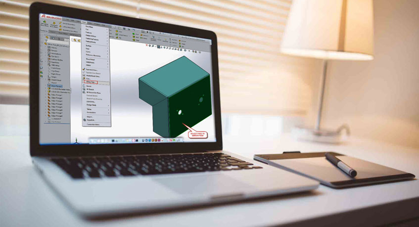
3D computer software models of sheet metal work components
When we sit down to think about a new sheet metal work project, we inevitably start by creating a 3D model of the component or assembly we are going to manufacture. Creating a 3D model has many advantages for us and our customers when we are planning to manufacture a new design or even an update to a past sheet metal component design. The ability to play with ideas in a software environment without having to commit to cutting or folding any sheet metal materials not only naturally saves time and money but it enables us to investigate different ideas quickly to find an acceptable solution to our customer’s needs and hopefully at a price that is right for both parties. The 3D sheet metal model can be exported and imported back in a STEP or SAT format enabling either our customers or us to initiate the design and update it in a free way until the final design is arrived upon. Some of the advantages of having a 3D model as the starting point for manufacturing are:
A) 3D images to aid communication of the design and understanding of the stages of manufacturing
The 3D model can be used to print out 3D views or wire frame images and dimensioned sections for bending, welding fabrication and inspection of the sheet metal work. These images can be used alongside the customers drawings where needed to communicate complex part details to the workshop to reduce the chances of confusion in production.
B) Material selection and thickness and its impact on the developed blank size for CNC laser cutting
The selection of the correct material and its thickness from a customized manufacturing database within the Bystronic sheet metal software system enables us to automatically create the developed blank to the correct size. As well as having the ability to create this blank size from the 3D model we can check it against the computer controllers on our Bystronic CNC press brake. We can check that the correct press brake tooling is used and the impact that will have on the developed sheet metal blank cut size and adjust it on the 3D model if necessary. This adjustment may be needed due to the bend radius of exact material specification used and can be physically checked with a sample piece of sheet metal to prove the design accuracy where needed.
C) The correct planning of manufacturing tolerances for production processes
The impact of manufacturing tolerance on sheet metal component design is important to achieve the correct fit of parts in the assembly. We have all see drawings with +/- 0.2mm tolerance for a part that is 50mm long and is being CNC sheared, which is fine. When the same drawing border is used for a 2000mm long component which is being CNC punched, bent up and welded we have to talk with the customer and investigate what is really important to them and adjust the 3D model where we can so that the sheet metal work produced will still be functional when it comes to assembly.
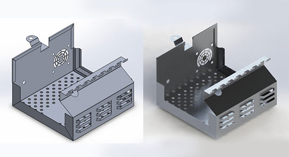
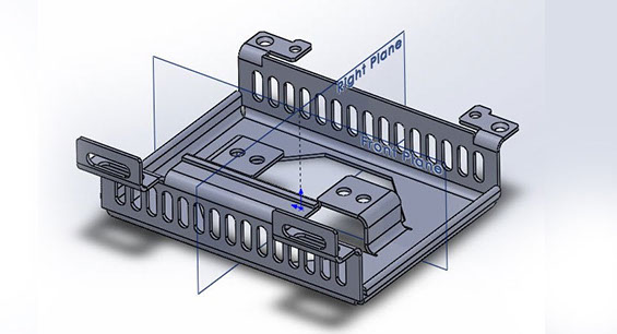
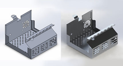
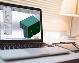
D) The fit of components such as the correct alignment of fixing holes between 2 or more components in any given assembly
As well as achieving the correct tolerance of sheet metal work from the 3D model the actual simple alignment of parts can be checked. The example show here of a sheet metal box and cover is a classic example. The box and cover may be presented to us as 2 separate 2D drawings on a DXG or DXF file or even a PDF image. By creating a 3D sheet metal model of the 2 parts together with the cover in position on the box we can check out for the customer any problems with the position of holes and the correct clearance for the cover to fit allowing for bend radius and powder coating thickness. If there is a problem at this stage it’s much easier to change the design slightly with the customer than manufacture a box and a lid both to the design drawings but not actually fitting together in assembly.
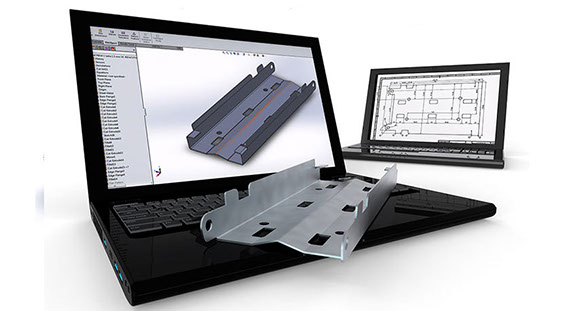
2D developed sheet metal blanks
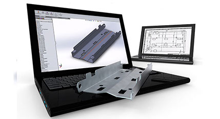
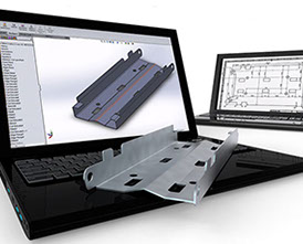
Now for us, having BySoft sheet metal software enables us to create a 2D blank (Image B) at the click of a mouse button. Not only is the sheet metal model unfolded correctly taking into account all the material type and sheet thickness details from the 3D model but any possible problems are highlighted at this stage as well. If a cut-out or hole is too close to a bend it will be highlighted in a different color for us so we can take the appropriate action. All the bend lines are also shown on the blank along with the direction and angle of each bend. This data can be useful to automatic setting the CNC press brake back-gauges or operators when they are manually programming the press brakes to bend the sheet metal components. We can also add dimensions and notes to the 2D developed blank drawing to enable inspection if required for important features or bend sizes in addition to the drawing from our customer.
At this stage, the 2D blank is a layout of the sheet metal components to be manufactured and also is machine specific. For us here at LaserSpike, we laser cut the blank with our Bystronic 4.4kW CO2 laser cutting machine.
2D developed sheet metal blanks with machine specific tooling
Once we have the developed sheet metal blank we can select which machine or machines we wish to use to manufacture the component. The big advantage of using BySoft software is that the 2D developed blank can be used to tool the part is several ways just with the click of a mouse button. The laser cutting parts can also be profiled with standard cutting “lead-ins” and an automatic tool path calculated to reduce head collision on the laser machine, heat build-up and the shortest route across the sheet to reduce overall laser cutting time in production.
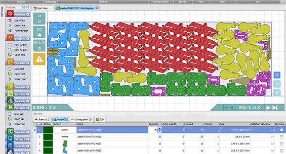
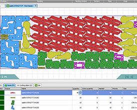
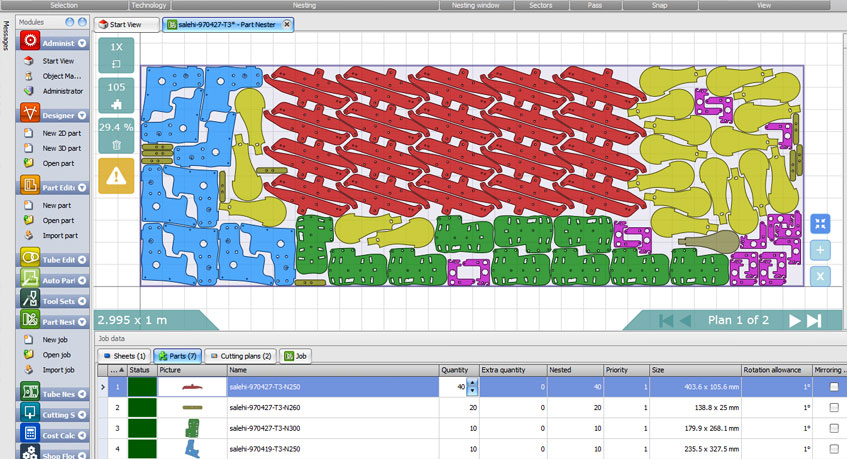
Sheet metal working laser cutting nests
Once the sheet metal blank has been tooled ready to produce a single part it needs to be applied to a sheet of metal ready for actual manufacture. The optimized pattern of components on the sheet can be automatically calculated by the BySoft software to achieve the best material yield from any given sheet size and quickest cutting path across the sheet to save time. The sheet used can be standard sheets which for us would be a choice of 3 sizes either 2.0M x 1.0M, 2.5M x 1.25M or 3.0M x 1.5M. If the volume is high enough then special sizes can be purchased in some materials to suit a component length and reduce wastage. For example, a sheet metal component blank that is 1.6M long would be wasteful with a 2.0M x 1.0M sheet but would be perfect have we purchased a 1.7M x 1.0M sheet. We can also use up remnants from past work or sheets in unusual shape (like circle, rectangle, etc.) to save buying in fresh material.
Sometimes we have to be able to force the blanks to have a certain orientation on the sheet. This may be ensuring about the grain of material when it comes to bending a component and has been specified by the customer. This is easy and we can control how much automation the software has and how much we need to layout the components by hand if needed to produce the correct nest.
The laser cutting next show here (Right Image) are of thin gauge parts that were not bent and had no grain effect on the sheet so we were free to get as many as possible from a sheet of metal with angular freedom of 5 degrees. You can see that the software is able to use a true shape nester to fit parts inside each other’s profile where possible to get the best use of material.
The power of sheet metal design
It is a fact that small changes cut production costs dramatically. Effective sheet metal design should not set out to eliminate welding, but instead, uncover the most cost-effective ways to manufacture a part. The best designs exploit the strengths of the welding process and minimize its weaknesses.
SHEET METAl DESIGN; These three simple words can have a tremendous impact on a company's bottom line. Ideally, effective, innovative, and creative sheet metal design ideas come early in the product design phase, because those ideas will influence the entire project, from the point of manufacturing to the product's end use.
A good designer must know all of the available shop technologies, and it's no secret that one of the most labor-intensive is arc welding. The sheet metal designer should never set out to eliminate welding; after all, arc welding often is the best joining option for the product. The designer's goal should be to maintain design intent while maximizing manufacturing efficiency, and reducing or simplifying welding often can help.
Good sheet metal design should reduce, simplify, and mistake-proof shop floor processes to ensure greater efficiency and, ultimately, dramatic cost reductions. In other words, manufacturing should be as easy as possible. If, say, a new design eliminates welding but makes the bending process incredibly complex, the process is moving backward.
Smart sheet metal design can ease downstream manufacturing. This design gives space for a mechanical locknut, eliminating the need for welding.
OPTIMIZATIOn
One rule of thumb: Bend long parts and weld short. CAM software for the press brake allows the designer to visualize all bends to discover which parts can be produced only by welding. Such software also allows him to try all bending sequence options and, in some cases, discover instances in which he can eliminate welding entirely. The designer must have a solid understanding of bend theory. This knowledge, combined with software, can be a real force in driving down costs.
The more knowledge a designer has, the more questions he asks. For example, it is almost impossible to put a 20mm flange on 8mm thick material; if the flange is required, it will probably be welded. But must the flange be the only 20mm? What is the design intent?
Consider similar circumstances, only now with thinner stock and shorter flanges. Are welded-on, 0.25-in.-high strips there to stiffen the assembly? If so, perhaps a rib or offset would suffice. In this case, the stiffening rib could be formed with an offset tool on the press brake (if the brake has sufficiently high tonnage for the job). Asking just a few questions may eliminate an entire process from manufacturing, and software helps designers quickly run through numerous possibilities.